
FX COOKBOOK #1: NODE-RED, DIGITAL INPUTS, AND OPERATOR INTERFACE
In Dev Blog 3, Shep walked us through getting a ShowIO device on our network and running a simple automated effect through QLab. QLab is a great program for sending cue sequences for a linear experience like a theatrical production or haunted house, but for something like an escape room I prefer an interface with more feedback and more granular control. If we can see which inputs and outputs are active in our escape room’s control system, we know what a team has solved and can assess how well they’re progressing. If we can remotely override a puzzle or door lock, it gives us flexibility at run time to help a slow group or bypass a malfunctioning puzzle (it happens to the best of us!).
All of these things would be relatively easy to accomplish with an industrial grade PLC and customized HMI, as long as you’re familiar with programming industrial controllers, human-machine interfaces, and have a few thousand bucks you’re eager to throw around. Alternately, you could do what I did in my past life and run override wires through the dusty drop ceilings of an old dentist’s office to create physical control panels, giving room hosts physical buttons and switches that directly controlled the electronics in the room. For a more modern and cost-effective solution, though, we can use existing open-source software to control a network of ShowIO devices with easy-to-follow logic and a bespoke user interface.
Across the first few FX Cookbooks, I’ll run through how I use a Node-RED server to send, monitor, and re-route OSC messages from ShowIO devices, as well as provide a guide to creating a quick user interface to see what all of your I/O is doing at a glance. That may sound like a lot, but don’t be intimidated: we’ll do all of this without writing a single line of code.
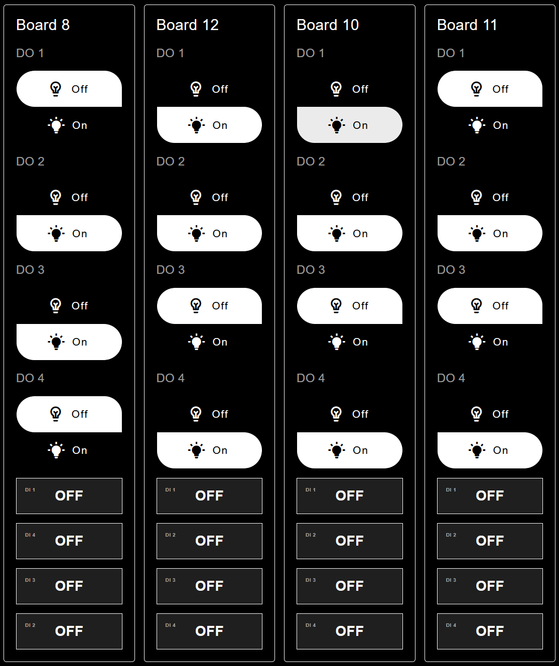
Node-RED user interface displaying the status of 4 ShowIO devices
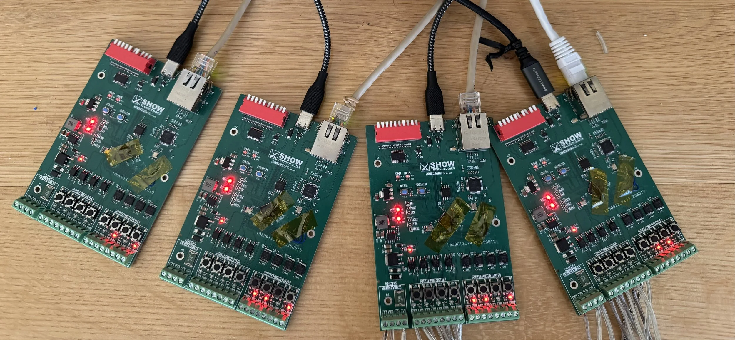
4 ShowIO devices whose output states correspond to the above device
FIRST STEPS
I’m going to assume you’ve read Shep’s excellent Dev Blog about getting your ShowIO device on your local area network (check out Development Blog #3, true believers! – TM), so I will skip most of that. If your device isn’t plugged in to power and Ethernet, go ahead and do it now—I’ll forget to mention it later, and it will save me the embarrassment.
Worth knowing is that I’ve put the computer that’s running Node-RED on the static IP Address 192.168.10.102, and I have 4 ShowIO devices on the LAN with sequential addresses starting at 192.168.10.20 (making them sequential isn’t necessary, but it makes keeping your network organized much easier.) You’ll see Linux terminal windows below because I’m running my interface on a Raspberry Pi, but this tutorial is OS-agnostic.
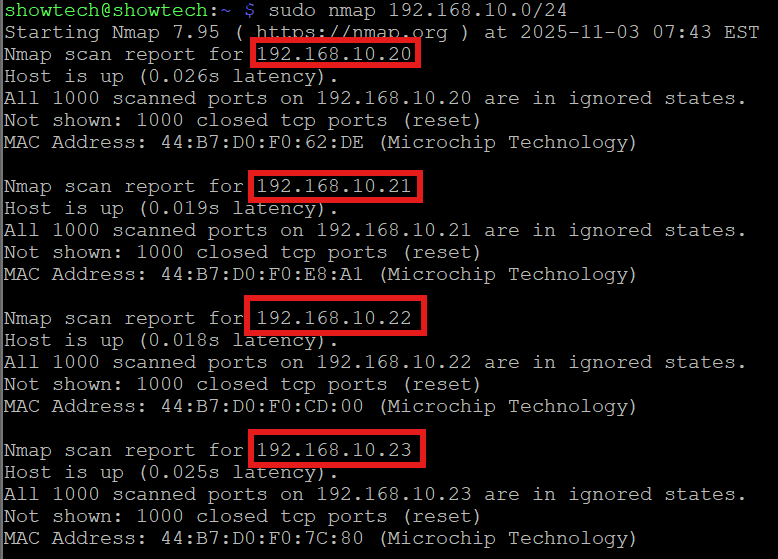
Terminal window showing 4 ShowIO device IP addresses
Installing and Configuring Node-RED
Next, you’ll need to install Node-RED on whatever computer you want to run your interface server. This does not have to be the same machine you are interacting with the interface from, you will be able to log in remotely. As I mentioned, I’m running my server on a Raspberry Pi, but I’ve done all the configuration from the Windows 11 machine I’m writing this Dev Blog on. This is just a taste of the power that modern networking brings to show control. Because you can run Node-RED on any device, I will let them walk us through it: https://nodered.org/#get-started. I’m going to elide some steps below in an attempt to keep the pacing of this post up-tempo, but make sure you follow all of the steps in the Node-RED getting started guide; it’s well-written and very helpful.
Once Node-RED is installed and running on the server machine, there are a few other setup tasks. First, I like to configure the Node-RED server to boot at startup on my Raspberry Pi. On Linux, that’s as simple as typing
>sudo systemctl enable nodered.service
MacOS and Windows have their own ways of doing this, but if you’re using a personal machine, consider if that’s the right approach for your application.
With our server running, we can access the Node-RED editor by simply typing the I.P. address followed by :1880 into a browser. If you’re editing and running Node-RED on the same machine, you can use the loopback address, 127.0.0.1.
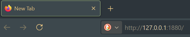
Point a new web browser tab at your loopback address if you’re running locally, or the IP address of the machine you’re hosting your server on.
Before we drop nodes in, we need a couple of additional nodes in our palette. Find the palette manager in the hamburger menu. Find and install @flowfuse/node-red-dashboard and node-red-contrib-osc.
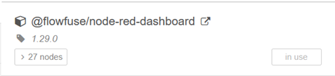
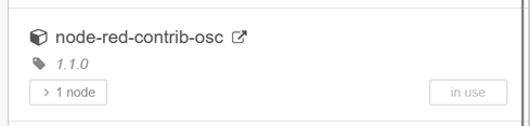
Node packages to install
The OSC node will let us translate messages from OSC to Node-RED and back again. The Node-RED dashboard will let us, unsurprisingly, make a dashboard. This will be the operator-facing portion of the UI.
First Flows
This has been a lot of computer setup work, so let’s blink some lights. We can start to develop a sound understanding of what we’re doing once we’re excited about integrated electronics in entertainment again. We only need to add four nodes to our Node-RED editor: 2 Inject nodes, one OSC node, and one UDP Out node. You can arrange them however you like, but I think you’ll find moving left-to-right, Inject > OSC > UDP Out, to be the most intuitive.
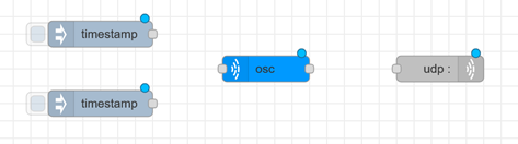
Requisite nodes for your first flow
We’ll need to connect and configure these nodes. Have the IP address for the ShowIO device you want to control handy. Before we start, each node has a “Name” field to make them easy to identify. This is extremely helpful, and we will use it shortly, but for now, leave this blank for every node. With no name attached, every node will display configuration data, making troubleshooting a small flow like this much easier.
Each Inject node will get a topic and payload corresponding to a ShowIO OSC address and argument. To turn on digital output 1, that will look like this:
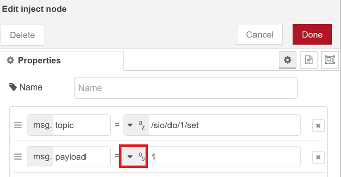
Inject node configuration. Note the data types for each message property.
Make sure to set the type of msg.payload to a number!
Your second Inject node will turn digital output one off. You’ll set the topic to the same OSC address, /sio/do/1/set, but set the payload to 0. You’ll plug those nodes into the left side of your OSC node. The OSC node needs no configuration. Now, configure your UDP Out node with your ShowIO device’s IP address and port 8888. You don’t need to change any other settings.
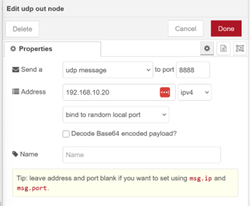
UDP Out node configuration
Connect the left side of the OSC node to the right side of the UDP Out node. Notice that each node helpfully displays the configuration you’ve applied; now is a great time to check that your OSC addresses, arguments, and IP address are all correct. Here’s one I made earlier:
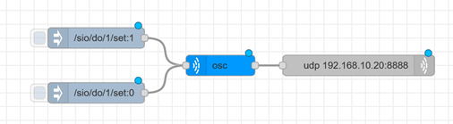
Your first flow
We can see that these nodes are configured correctly, so there’s nothing left to but to press deploy and Inject the OSC messages to see your digital output turn on and off. Thrilling! If we want to control all 4 digital outputs, this scales easily:
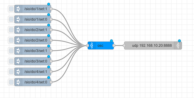
Expanded digital output control flow
Once we’ve established that all of our DOs are both working and fun to play with, it’s a good time to start thinking about the user interface. The node labels are helpful for quick debugging, but it’s not obvious at a glance what each piece does (it certainly won’t be obvious to the high schooler you’re paying to run your escape rooms!) Let’s assume this device will be part of the control system for a tasteful “First Thanksgiving”-themed escape room. We’ll put two magnetic locks, an LED spotlight, and a solenoid for a parachute key drop and label our flow accordingly.
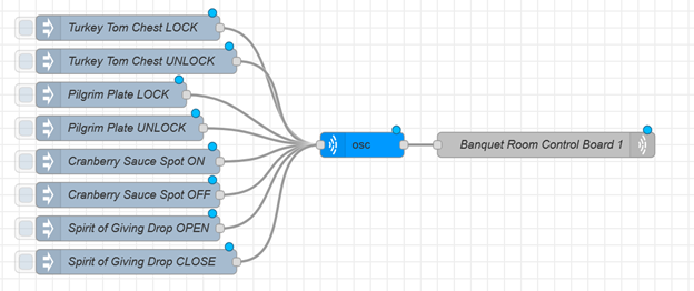
Digital output flow, relabeled for our tasteful “First Thanksgiving” escape room
Now we have the beginnings of a user interface. It isn’t the slick, Show Technologies-branding-guide-approved UI I promised at the beginning of this post, but it’s completely usable for manually triggering digital outputs.
To understand why we’re using Node-RED as our server, it’s worth revisiting Open Sound Control on a conceptual level. An OSC message has an address, a “type tag string”, and some number of arguments (possibly zero.) The OSC messages address and arguments map very nicely to the Node-RED message’s topic and payload. The OSC node is our translator; it adds the type tag string to outgoing Node-RED messages and removes it from incoming OSC messages so we can route and manipulate our data easily. Next week, we’ll look at reading our device’s digital inputs, routing messages to different devices and programs, and finally building the user interface I advertised at the top of this post.
Want to chat about ShowIO? Reach out at tmarshall@show-technologies.com!